
Modbus RTU, ASCII, and TCP with SerialTool
What is Modbus
Modbus is a serial communication protocol created in 1979 by Modicon® (now part of Schneider Electric) to connect its programmable logic controllers (PLCs). It has become a de facto standard in industrial communication and is one of the most widely used connection protocols globally among industrial electronic devices. Modbus is a royalty-free protocol declared as specifications on The Modbus Organization's website.
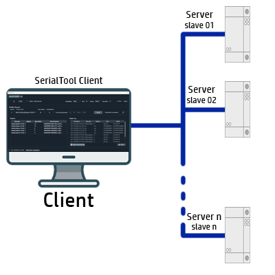
In simple terms, it is a method used to transmit information over serial lines between electronic devices. The device requesting information is called the Modbus Client, and the devices providing information are Modbus Servers. In a standard Modbus network, there is one client and up to 247 servers, each with a unique server address from 1 to 247. The client can also write information to the servers.
Originally designed for industrial use, over time, this protocol has been adopted in various sectors, becoming one of the most widespread protocols. Even today, after more than 40 years, it is available in many devices, such as operator panels, PLCs, home automation, and even integrated into simple devices like Arduino.
Modbus RTU and ASCII Transmission via Serial
Communication, when the protocol was created, was intended to be used via a serial port, which is why it has been implemented in SerialTool. Modbus is often used to connect a supervisory computer with a remote terminal unit (RTU) in supervisory control and data acquisition (SCADA) systems. Depending on the format in which the data is transmitted, the protocol is divided into:
- MODBUS RTU - data is transmitted in hexadecimal format.
- MODBUS ASCII - data is transmitted in ASCII format.
Error control differs in the two cases; in MODBUS RTU, a Cyclic Redundancy Check (CRC) is used and sent after the commands, while in MODBUS ASCII, a Longitudinal Redundancy Check (LRC) is sent after the commands.
Modbus TCP Transmission
In 1999, "Modbus TCP" was developed, a standard dedicated to networks using the TCP/IP protocol suite. It is essentially a version of Modbus serial RTU based on TCP/IP, enabling communication over internet/intranet networks. In recent years, the TCP/IP version is increasingly used because it is open source, easy to implement, has low development costs, and has minimal hardware support.
Error control differs in the two cases; in MODBUS RTU, a Cyclic Redundancy Check (CRC) is used and sent after the commands, while in MODBUS ASCII, a Longitudinal Redundancy Check (LRC) is sent after the commands.
The Modbus TCP/IP protocol uses binary encoding of data and the TCP/IP error detection mechanism. Unlike the serial Modbus, the TCP/IP version is connection-oriented and allows concurrent executions on the same slave or on multiple devices. Modbus TCP/IP also uses the master-slave paradigm, and this communication uses four types of messages.
Modbus is positioned at layer 7 in the ISO/OSI stack (Application Layer), defining message formatting called framing and the mode of transmission of data and control functions. Communication occurs through the client-server paradigm. The protocol defines a Protocol Data Unit (PDU) that does not depend on the underlying communication layer. The Application Data Unit (ADU) introduces additional fields for addressing and error control.
SerialTool Modbus Client
SerialTool supports RTU, ASCII, and Modbus TCP transmission modes to provide the maximum professional flexibility of a Modbus Client.
SerialTool also offers the option to send Raw commands to facilitate any developer's needs.

Screen with the log of sent commands
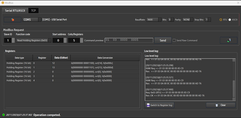
Screen with low-level commands sent
Modbus Functions
Here are the functions that SerialTool implements for the Modbus protocol.
| Function Code | Action | Table Name |
|---|---|---|
| 0x01 | Read | Discrete Output Coils |
| 0x02 | Read | Discrete Input Contacts |
| 0x03 | Read | Analog Output Holding Register |
| 0x04 | Read | Analog Input Registers |
| 0x05 | Write Single | Discrete Output Coil |
| 0x06 | Write Single | Analog Output Holding Register |
| 0x0F (dec 15) | Write Multiple | Discrete Output Coils |
| 0x10 (dec 16) | Write Multiple | Analog Output Holding Registers |
Modbus Data Structures
Information is stored in the Server device in four different tables. Two tables store discrete on/off values (coils), and two store numeric values (registers). Both coils and registers have a read-only table and a read-write table. Each table has 9999 values. Each coil or contact is 1 bit and has a data address between 0000 and 270E. Each register is 1 word = 16 bits = 2 bytes and also has a data address between 0000 and 270E.
| Coil/Registers numbers | Data Addresses | Type | Table Name |
|---|---|---|---|
| 1-9999 | 0x0000 to 0x270E | Read/Write | Discrete Output Coils |
| 10001-19999 | 0x0000 to 0x270E | Read Only | Discrete Input Contacts |
| 30001-39999 | 0x0000 to 0x270E | Read Only | Analog Input Register |
| 40001-49999 | 0x0000 to 0x270E | Read/Write | Analog Output Holding Register |