Virtual COM Port (VCP)
Creator of Virtual COM Port (VCP) pairs
Video Tutorial Available
A video tutorial is available by clicking this link.
SerialTool - VCP (Virtual COM Port)
The images on this page may differ from newer versions of SerialTool.Thanks to the implementation of a powerful kernel driver, it is possible to create virtual COM port pairs, and more: SerialTool offers ready-to-use utilities such as COM Splitter, COM Sniffer and COM to Network.
Since version 2.2.0, SerialTool provides Windows users the ability to quickly, flexibly, and reliably create virtual COM port pairs through the Virtual COM Port feature.
This feature (with some limitations in the FREE version) is ideal for those who need to experiment with embedded applications or interface with legacy devices whose software is no longer maintained.
Thanks to the implementation of a powerful kernel driver, it is possible to create virtual COM port pairs, and more: SerialTool offers ready-to-use utilities such as COM Splitter, COM Sniffer, and COM to Network.
What is a Virtual COM Port on Windows?
A virtual COM port (VCP) is a software interface that emulates the behavior of a traditional RS-232 serial port, allowing applications to communicate with each other or with simulated devices without the need for physical hardware. On Windows, these ports are recognized by the operating system as real COM ports, ensuring compatibility with software that requires serial connections.
The virtual COM port reproduces a null-modem connection, which can also be simulated with a physical cable by crossing the TX-RX lines of one serial port (e.g., COM10) with those of a second serial port (e.g., COM11). With TX from COM10 connected to RX of COM11 and vice versa, data sent by either port is received by the other. This is why it's referred to as a COM port pair.
Virtual COM ports always refer to a pair created internally in the operating system by a kernel driver and virtually linked together.
Among its various uses, the virtual COM port is commonly used in HAM radio setups, GPS signal splitters, embedded system debugging, or prototyping with Arduino. In some cases, older software that only connects to fixed COM ports or unsupported baud rates can be reused on modern systems thanks to virtual COM ports.
Advantages of Virtual COM Ports
Here are some benefits of virtual COM ports:
- Development and Testing: Ideal for developers who need to simulate serial communication between devices during development and debugging phases.
- Legacy Device Integration: Allows software designed for traditional serial ports to work on modern hardware without physical serial ports.
- Network Communication: Enables serial data transmission over TCP/IP networks, extending serial communication beyond physical limitations.
Virtual COM Port Management
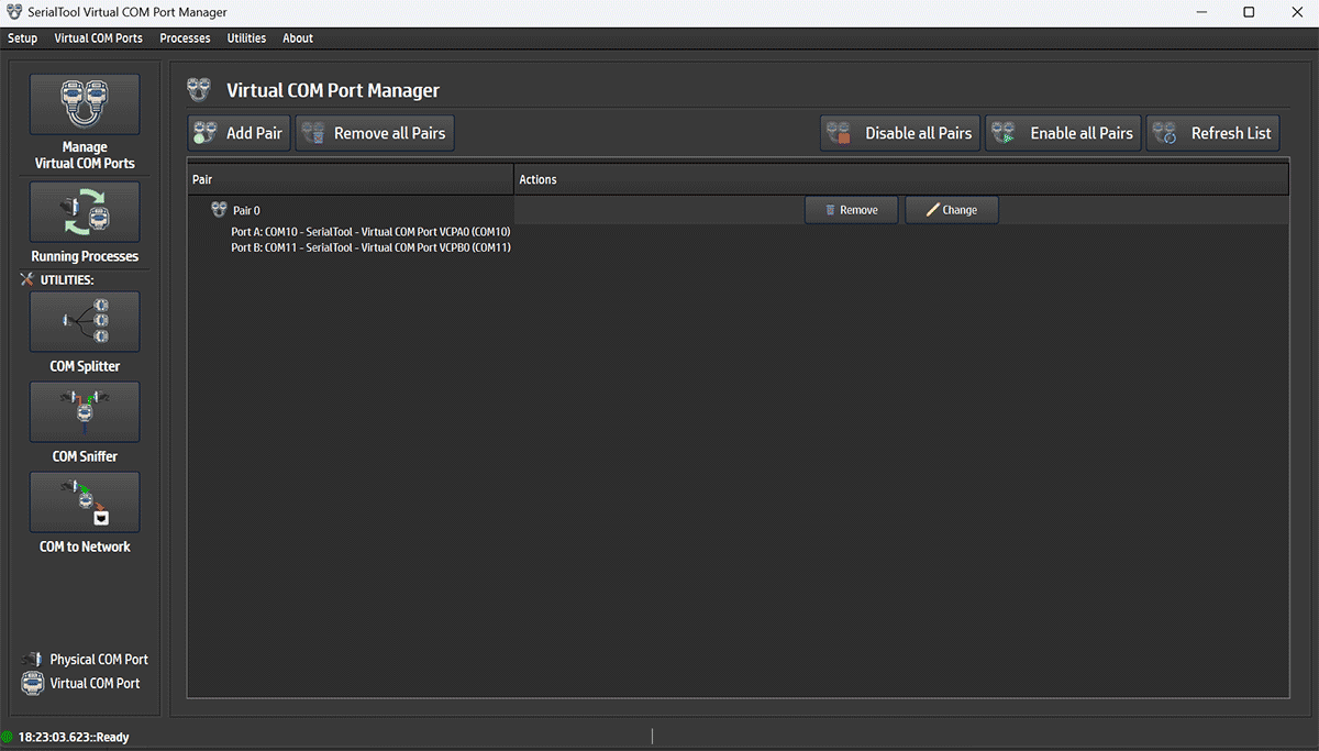
Virtual COM Port Manager
From the Virtual COM Port Manager menu you can manage virtual COM ports.
- Add Pair: Add a new pair of virtual COM ports.
- Remove all Pairs: Remove all virtual COM ports at once.
- Disable all Pairs and Enable all Pairs: Disable or enable all virtual COM ports. The ports remain installed but are no longer available.
Each virtual COM port pair can be configured by modifying the logical signal connections using the Change button.
Virtual COM Port Configuration
Here is what the virtual COM port configuration menu looks like.
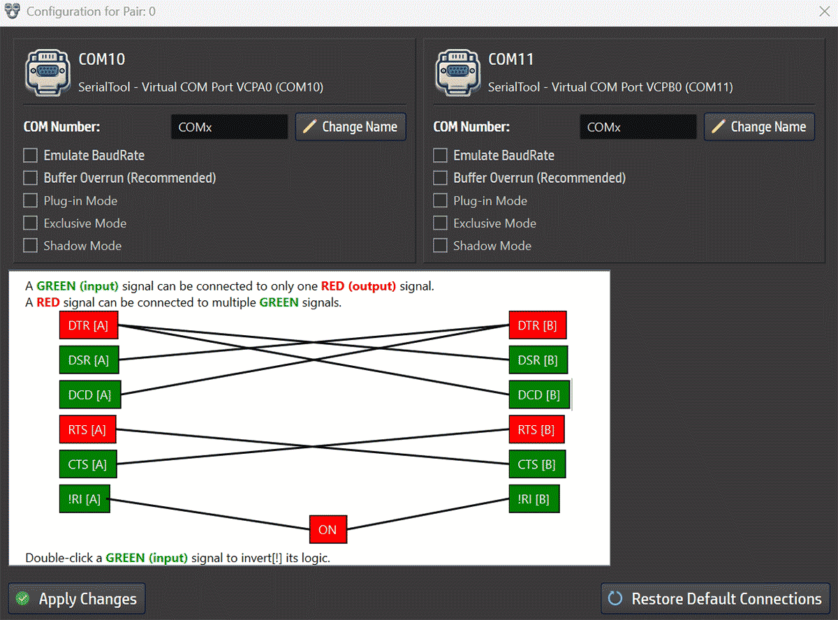
Virtual COM Port Configuration
From the configuration screen you can change the number of each COM port compared to its initially assigned value. For example, COM10 can be renamed to COM21 or any other value allowed by the OS, as long as it is not already in use — see official Microsoft documentation.
You can also change the logical behavior of the virtual COM port signals.
The default configuration is a classic null-modem setup where red signals (DTR and RTS) are outputs, and green signals (DSR, DCD, CTS, and RI) are inputs.
Input signals can only be connected to one output signal, while output signals can be connected to multiple input signals.
Input signals can also be logically inverted by double-clicking their box. A "!" will appear at the beginning of the signal name to indicate it is logically negated relative to its output.
TX and RX signals, although not shown or editable, are always crossed between the ports.
Here are more specific descriptions of COM port signals:
In a null-modem setup, DTR is often connected to DCD so the device can simulate carrier detection, indicating the line is "active."
RTS/CTS – Request To Send / Clear To Send
This pair of signals implements a hardware flow control protocol:
- RTS (Request To Send): Sent by the DTE to request permission to transmit data.
- CTS (Clear To Send): Sent by the DCE to authorize the transmission.
This signal indicates to the terminal: "Yes, a real connection to another device has been detected."
In null-modem setups, DCD is often simulated by linking it to DTR or other signals to force carrier detection.
It is symmetrical to DTR and acts as confirmation that the communication device is active and ready.
This signal indicates that the phone associated with the modem is ringing. It is temporarily activated (typically at -15V) whenever an incoming call is detected.
On real modems, it is tied to the telephone line. In null-modem configurations, this signal is often unconnected, as it is not relevant.
For standard application testing, it is recommended not to modify the default signal connection configuration unless strictly necessary or unless you fully understand the implications.